Defining Process Flow Objects
|
Topics: |
Process flow objects are the major components of a process flow. IIT Designer provides control objects, which direct the movement of the input document, and execution objects, which perform a specific task with the document. You will configure each object as you add it to the process flow. This section describes each object provided in Designer and explains how to configure these objects to perform the tasks that you require.
Designer provides the following process flow objects to build a process flow:
|
Start Object |
Process Object |
|
End Object |
Web Service Object |
|
Join Object |
SQL Object |
|
Junction Object |
ETL Object |
|
Decision Switch Object |
BI Object |
|
Decision Test Object |
ReportCaster Object |
|
Set Object |
Email Object |
|
Sync Object |
FTP Object |
|
Debug Object |
File Object |
|
Service Object |
HTTP Object |
|
Iterator Object |
Emitter Object |
|
Transform Object |
Queue Object |
Start Object
All process flows must begin with the Start object. Therefore, it is automatically added to the workspace when you create a new process flow. A process flow can contain only one Start object.
The Start object icon is shown below.
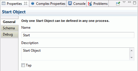
To view the properties of a Start object in a process flow, right-click the Start icon in the workspace and select Properties from the drop-down list. The Start Object properties are displayed in the bottom of the Workspace.
Note: You can also change the Start object parameters from this dialog box.
The Properties window consists of the General, Schema, and Debug tabs. The General tab is expanded below. It displays the name and a description of the Start object. To view information about the Start object schema or debug setting, select this tab.
The Schema tab, shown in the following image, allows you to select and view a schema that is available from the current server configuration. This schema maps to the input document expected by the process flow.
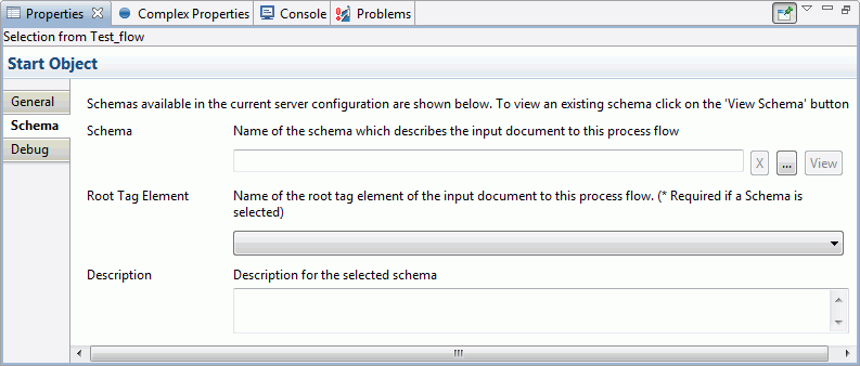
Note: Schema is needed if you intend to expose the process flow as a web service.
If you want to designate a schema for the Start object, select a schema from the Schema drop-down list. To view the selected schema in a separate window, click View.
The Input Schema Value field reflects the schema selection made in the Schema tab. Select or type a value in the Root Tag Element field. An XML root tag is the beginning XML tag and it identifies the XML document. For example, <phonebook>.
End Object
The End object terminates the process flow. All processes must terminate with at least one End object. There can be multiple End objects in a single process flow. The End object icon is shown below.
When you add an End object to the flow, the New End Object dialog box opens, as shown in the following image.
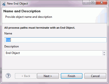
Type a Name to identify the End object and, optionally, type a brief Description. The Design mode option allows you to include the object in the process flow as a place marker, that is, without defining its parameters. Click Next to continue configuring the object.
The End Object Schema dialog box opens, as shown in the following image.
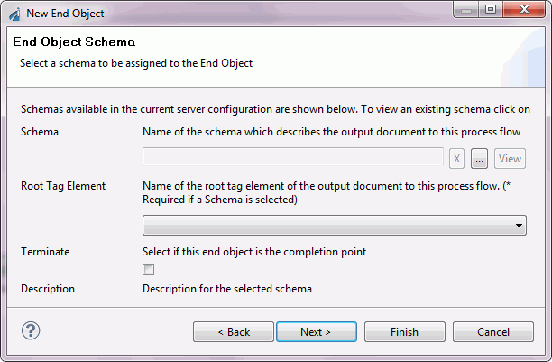
Note: Schema is needed if you intend to expose the process flow as a web service.
If you want to expose the process flow as a web service, select a schema for the End object from the Schema drop-down list. Otherwise, select None. If you want to view a schema you selected, click View. The schema appears in the browser.
The End object properties are:
- Root Tag Element. Enter or select the name of the root tag element of the output document for the current process flow.
- Terminate. Select false to pass the document to the listener, or select true to suppress transmission of the document to the listener. If your process flow provides all of the output necessary for your application, then you can set Terminate to true in order to bypass the outlets associated with your channel. You can use multiple End objects with different settings in a process flow to direct document flow behavior.
When you have finished entering, or selecting, the property values, click Finish. The End object icon appears in the workspace.
The Control Objects
|
Topics: |
The Control objects for a Designer process flow are:
- Decision Switch object
- Decision Test object
- Join object
- Junction object
- Set object
- Synch object
The following sections describe how to define each Control object as you include it in a process flow.
Decision Switch Object
The Decision Switch object evaluates the contents of a document or a variable, and routes the document accordingly, similar to the switch/case construct of other programming languages. The main difference is that the document can match multiple cases simultaneously when using an XPath switch expression. The Decision Switch object icon is shown below.
When you add a Decision Switch object to a flow, the New Decision Switch Object dialog box opens, as shown in the following image.
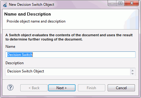
Type a Name to identify the Decision Switch object and, optionally, type a brief Description. The Design mode option allows you to include the object in the process flow as a place marker, that is, without defining its parameters. Click Next to continue configuring the object.
The Switch Expression dialog box opens, as shown in the following image.
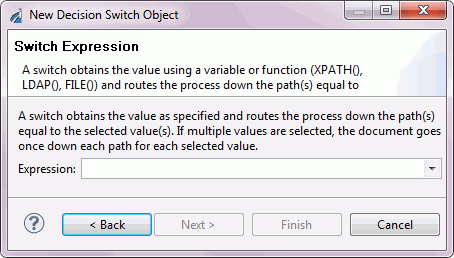
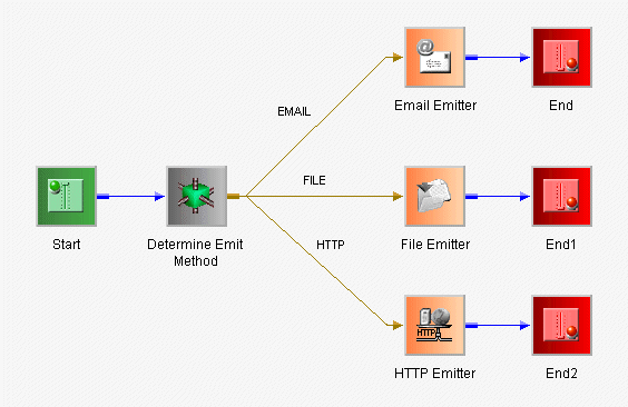
The Decision Switch object can direct the document down one or more alternate paths based on the value of the switch expression. In the following example, the document contains a value indicating the protocol(s) through which it should be routed (HTTP, EMAIL, FILE). To accomplish this, an XPath is constructed to capture the switch value from the document. You can also switch on computed conditions by using a variable that was set to one of your case values earlier in the process flow. For illustrative purposes, the following XML document has all switch values represented.
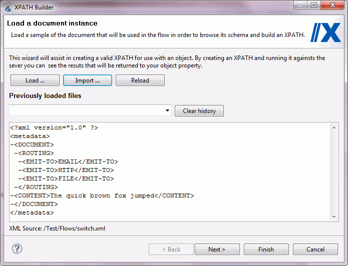
Click Next to build the XPath expression. The following image shows the expression in the XPath Builder.
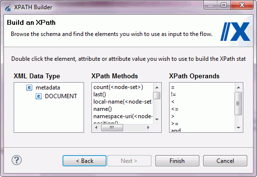
When you have finished constructing your XPath expression, click Next to continue to the Switch Cases dialog box.
Add the Switch Case values and descriptions to the table. Each switch case creates a named outlet leaving the Decision switch node. When the current switch value is equal to a switch case, the document will be sent down the corresponding edge for further processing. If the XPath expression recovers multiple switch values, the document will be sent down multiple edges simultaneously. See Building Relationships Between Objects for details on drawing edges that connect to the named outlets of a Decision Switch Case.
Click Finish. The Decision Switch object icon appears in the workspace.
The following image shows the finished process flow containing the Decision Switch example.
Decision Test Object
The Decision Test object evaluates the contents of a document, returns a true or false condition, and routes the document to the next object(s) in the process based on that result. You will define the evaluation and routing criteria through the Decision Test object properties.
The Decision Test object icon is shown below.

When you add a Decision Test object to a flow, the New Test Object dialog box opens, as shown in the following image.
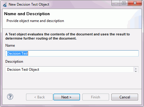
Type a Name to identify the Decision Test object and, optionally, type a brief Description. The Design mode option allows you to include the object in the process flow as a place marker, that is, without defining its parameters. Click Next to continue configuring the object.
The Test Operands dialog box opens, as shown in the following image.
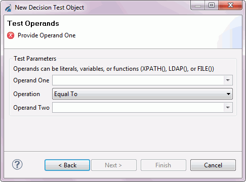
Operands in the Test Object can be literals, variables, or XPath expressions. The available comparison operations are: Is Null, Not Null, Equal To, Not Equal To, Greater Than, Less Than, Greater Than or Equal to, Less Than or Equal to.
Select the test parameters and click Next. The Value Occurrences dialog box opens, as shown in the following image.
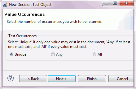
When using an XPath expression, many values can be retrieved from the document. This dialog box allows you to specify how the test comparison should handle multiple values.
Select a test occurrence:
- Unique. Only one value can exist in the document.
- Any. At least one value must exist in the document.
- All. Every value must exist in the document.
Click Finish. The Decision Test object icon appears in the workspace.
The Decision Test object has two pre-defined custom outlets, ‘true’ and ‘false’, from which you can draw edges. See Building Relationships Between Objects for details on drawing edges that connect to the named outlets of a Decision Test case.
Join Object
The Join object combines two or more documents into a single document. The single document then proceeds to the next object in the process flow. For example, if you have two XML documents:
A:
<A> ... </A>
and B:
<B> ... </B>
The Join object creates the following output:
<JOIN>
   <A>
    .
    .
    .
  </A>
  <B>
    .
    .
    .
  </B>
</JOIN>
Caution: Use caution when mixing Join and Junction objects in a process flow. When a Join object is located after a Junction object, results can be unpredictable.
The Join object icon is shown below.
When you add a Join object to the flow, the New Join Object dialog box opens, as shown in the following image.
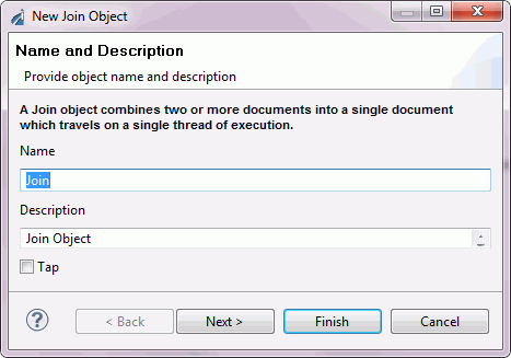
Type a Name to identify the Join object and, optionally, type a brief Description. The Design mode option allows you to include the object in the process flow as a place marker, that is, without defining its parameters. Click Next to continue configuring the object.
The New Join Object - Timeout dialog box opens, as shown in the following image.
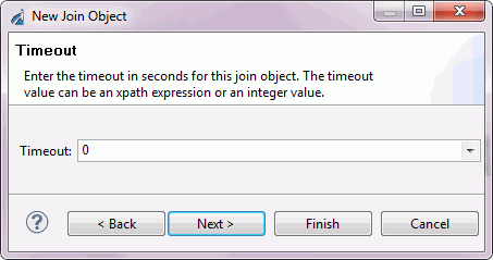
Timeout is the amount of time (in seconds) that the Join object will wait to receive the documents it must join. The timeout count begins when the first document enters the Join object. If the Join receives all of the documents before the timeout period ends, the join process continues. If all documents needed to satisfy the join are not received, then a status document is generated and sent along the OnTimeout edge.
Select a Timeout value from the Value drop-down list and click Finish.
The Join object icon appears in the workspace.
Junction Object
A Junction object joins two or more paths of execution into a single path. It does not join documents that travel along the path. For example, if you have five distinct paths that run to a certain point, and then all paths execute the same logic, use the Junction object to consolidate the flow at the point of common execution.
Caution: Use caution when mixing Join and Junction objects in a process flow. When a Join object is located after a Junction object, results can be unpredictable.
The Junction object icon is shown below.
When you add a Junction object to a flow, the New Junction Object dialog box opens, as shown in the following image.
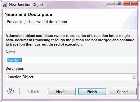
Type a Name to identify the Junction object and, optionally, type a brief Description. The Design mode option allows you to include the object in the process flow as a place marker. Click Finish. The Junction object icon appears in the workspace.
Note: There are no parameters associated with the Junction object.
Set Object
|
Topics: |
The Set object initiates one or more process events that Synch objects are waiting on. Set and Synch objects are used to suspend and resume the execution paths of a process flow.
The Set object icon is shown below.
When you add a Set object to a flow, the New Set Object dialog box opens, as shown in the following image.
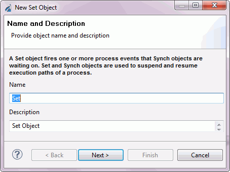
Type a Name to identify the Set object and, optionally, type a brief Description. The Design mode option allows you to include the object in the process flow as a place marker, that is, without defining its parameters. Click Next to continue configuring the object.
The Define Events dialog box opens, as shown in the following image.
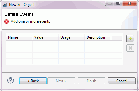
Add one or more events that can be used to meet conditions defined in one or more Synch objects. Click the Plus button and type an event name in the Name column. Then, double-click and select a value and usage from the Value and Usage drop-down lists, and type a description of the event in the Description column.
When you finish defining the events, click Finish. The Set object icon appears in the workspace.
Handling Header Information
Header information is "metadata" carried along with the actual message payload, but it is not strictly a part of it. Many protocols, such as HTTP, IBM WebSphere MQ, and JMS, provide header information support, although often under names such as "user data" or "side data."
The server makes received header information available in special registers that take the name of the header field. For example, a message received through HTTP will usually carry a header field of “content-type,” which can be referenced as sreg("content-type"); these registers carry the type of ‘header’.
When messages are emitted, special registers of type header are associated, with the message as appropriate to the protocol. To add a special register of type header, the Set object can be used in a process flow. Set the register type to ‘header’.
The following image shows the Define Events dialog box (accessed during the Set object configuration) defining an event named MyHDR.
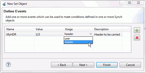
Incoming headers are loaded into header special registers and emitted message headers are drawn from such registers. This provides a convenient method of transferring messages with headers across protocols. The ultimate treatment of header information is the responsibility of the application developer.
Synch Object
The Synch object waits for a condition to be met, such as the expiration of a time limit or the evaluation of an expression as 'true'. The conditions are based on the events created through the Set object.
The Synch object icon is shown below.
When you add a Synch object to a flow, the New Synch Object dialog box opens, as shown in the following image.
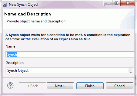
Type a Name to identify the Synch object and, optionally, type a brief Description. The Design mode option allows you to include the object in the process flow as a place marker, that is, without defining its parameters. Click Next to continue configuring the object. The Expression Builder dialog box opens, as shown in the following image.
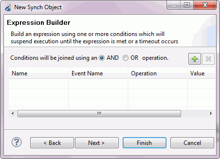
To build a Synch expression, click the Plus button. The default, Condition1, appears under the Name column, as shown in the following image.
You can change the name and select the Event Name, Operation, and Value for the new condition. The Event Name drop-down list consists of the events defined in the process flow Set objects. Add as many conditions as required. Above the condition parameters, select the relationship between these conditions as an And or OR operation.
To delete a condition, select the condition, and click the X above the list of conditions.
Click Next. The Timeout dialog box opens, as shown in the following image.
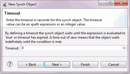
Type a timeout value (in seconds). This is the time period for which the Synch object will wait for the expression to be evaluated as 'true'. A value of zero (0) means that the Synch object will wait indefinitely.
Click Finish. The Synch object icon appears in the workspace.
The Execution Objects
|
Topics: |
The following sections describe how to define each Execution object as you include it in a process flow.
BI Object
The BI object allows the process flow to run a WebFOCUS report.
The BI object icon is shown below.
When you add a BI object to a process flow, the New WebFOCUS Object dialog box opens, as shown in the following image.
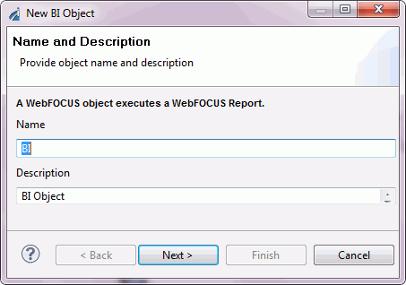
Type a Name to identify the BI object and, optionally, type a brief Description.
Note: As a convenience, you can launch Developer Studio and Managed Reporting, two external WebFOCUS tools, by clicking the corresponding buttons in this dialog box. Designer automatically determines the presence and location of these tools. For details on using these tools, see the Developer Studio documentation set and the WebFOCUS Managed Reporting End User’s Manual.
Once you have named the new WebFOCUS object, click Next. The WebFOCUS Connect dialog box opens, as shown in the following image.
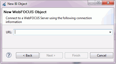
Select or type the URL of the target WebFOCUS server and click Next.
Note: If you choose to use a localhost address, be aware that this URL is relative to the iWay Service Manager, not to the machine running Designer.
The next WebFOCUS Connect dialog box opens, as shown in the following image.
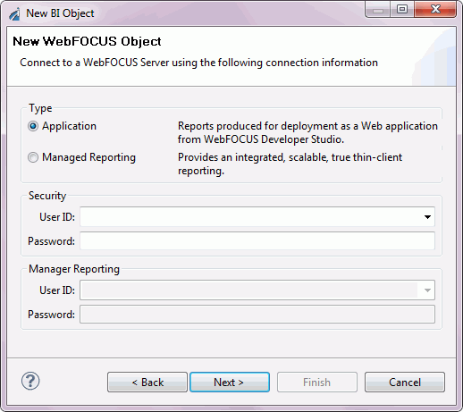
Select the source of the WebFOCUS report you want to include. Consult the WebFOCUS documentation or your WebFOCUS site administrator to determine where your reports are located. Type your login credentials for WebFOCUS and click Next.
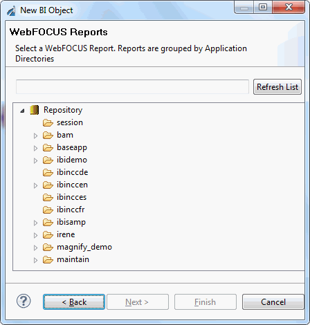
If you have chosen Application in the previous dialog box, the WebFOCUS Reports dialog box opens, as shown in the following image.
If you selected Managed Reporting in the previous dialog box, you will see a dialog box similar to the following image.
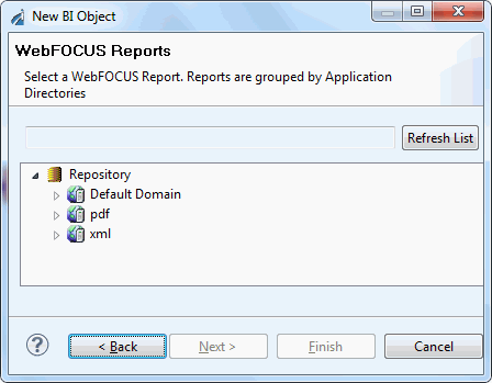
In either case, navigate the hierarchy and select the desired report, then click Next. The Object Properties dialog box opens, as shown in the following image.
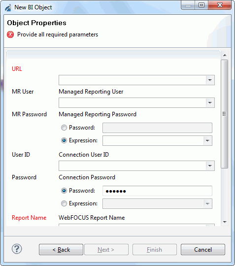
Verify that all the parameters are correct and click Finish.
The BI Object appears in the workspace.
Once a BI Object exists, you can configure it to accept dynamic properties. To do this, open the BI object for editing and select the Properties tab. Replace one or more of the properties with a special register (SREG), an XPath statement, or with any other iWay Functional Language statement. For information on using variables and Xpaths, see Using Variables and XPath.
Email Object
The Email object allows a process to send or receive an email with one or more attachments. The Email object icon is shown below.
When you add an Email object to a process flow, the New Email Object dialog box opens, as shown in the following image.
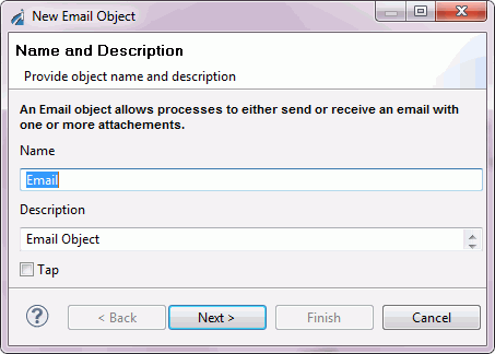
Type a Name to identify the Email object and, optionally, type a brief Description.
Click Next. The Email Object Type dialog box opens, as shown in the following image.
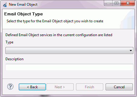
Select the Email type from the Type drop-down list. The Standard Email Client emits an email with one or more attachments. The Attachment Extractor identifies an attachment extractor to be used on a flow that is deployed to an email listener.
Click Next. The Object Properties dialog box opens. The following image shows the Properties dialog box for the Standard Email Attach Agent email type.
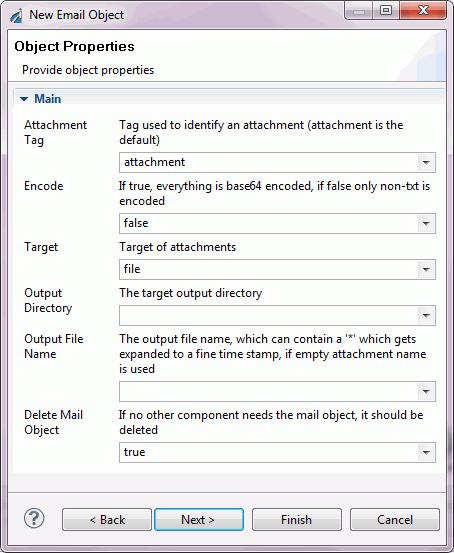
Type or select the property values to define the Email object and click Finish. The Email object icon appears in the workspace.
Emitter Object
The Emitter object enables behavior in your process flow equivalent to configuring an emitter through the iWay Console. In other words, the action of the Emitter is delayed until after all steps in your process flow are performed and all post‑processing of the document is complete. A consequence of this delayed execution is that if there is an error during processing, and even if an error occurs in the flow after the Emitter, the emit will not occur. The significance of the placement of the Emitter object in your process flow is that it determines the routing information that will be used when the emission ultimately occurs. In contrast, the version of the document that is dispatched by the Emitter is the result of all processing and, therefore, is not necessarily the version at the point in the flow where the Emitter object is placed.
When you add an Emitter object to a process flow, the New Emitter Object dialog box opens, as shown in the following image.
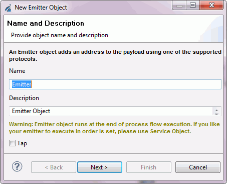
Type a Name to identify the Emitter object and, optionally, type a brief Description.
Click Next. The Emitter Type dialog box opens, as shown in the following image.
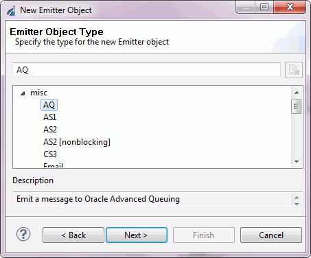
Select the type of emitter the object will bind to; a predefined emitter, a local instance based on an existing template, or a protocol definition.
Select a protocol from the Protocol drop-down list. The choices are:
- AQ. Emit a message to Oracle Advanced Queuing.
- AS1. Emit a message over SMTP using AS1 specifications.
- AS2. Emit a message over HTTP using AS2 specifications.
- AS2 [nonblocking]. Emit a message over HTTP using AS2 specifications.
- CS3. iWay Data Server access.
- Email. Emit a message to an SMTP host.
- FTP[S] Client. Emit a message using FTP to a specific directory on a defined host.
- File. Emit a message as a file to a specified directory.
- HL7LLP. Emit a message via TCP.
- HTTP 1.0 [deprecated]. POST a message to a defined host:port/action.
- HTTP 1.1 [nonblocking] (nhttp). POST a message to a defined host:port/action.
- Internal Queue. Internal queue listener. Internal queues are used to pass messages between channels within a configuration. They facilitate the modularization of message processing.
- Java Message Service (jmsq). Emit a message to a specified Java Message Queue or publish to a Topic.
- MQ. Emit a message to a specified MQ Series queue.
- Passthru. A dummy emitter to use as a placeholder during development.
- SFTP. Emit a message using SFTP to a specific directory on a defined host.
- Sonic. Emit a message to be a specified SONIC message queue, or publish to a Topic.
- TCP. Emit a message through TCP.
- Tibrv. Emit a message to a Tibco Rendezvous queue.
- Print. Emit a message using a specified print server using IPP.
For more information on these protocols, see the iWay Service Manager Protocols Guide.
Click Next. The Object Properties dialog box opens. The properties that appear depend on the Emitter Type you selected. The following image is the dialog box that appears when you select the AQ protocol.
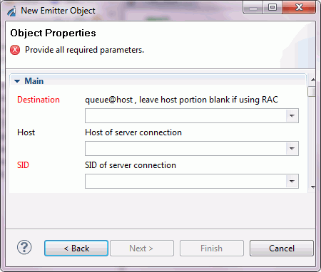
Note: All fields with titles in red are required parameters.
When you are finished defining the emitter, click Finish. The Emitter object icon appears in the workspace.
ETL Object
The Extract Transform Load (ETL) object executes an iWay DataMigrator flow. iWay DataMigrator supports traditional batch ETL and trickle-feed ETL for real-time data updates. Using the ETL object in a process flow enables:
- Real-time data warehousing. Utilizing trickle-feed ETL, data can be acquired, cleansed, and updated without waiting for a nightly batch window.
- Process-driven business intelligence. This approach may use any of the other data integration mechanisms, but adds two important capabilities: the ability to monitor business processes and detect relevant events in them, and the ability to participate in business processes and contribute information to them.
- ETL exposed as web services . Allows ETL jobs to participate in enterprise SOA solutions.
The ETL object icon is shown below.
When you add an ETL object to a process flow, the New ETL Object dialog box opens, as shown in the following image.
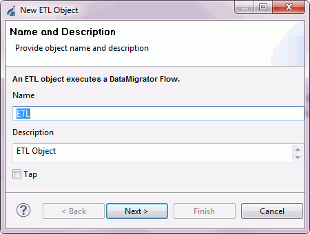
Type a Name to identify the ETL object and, optionally, type a brief Description (optional).
Click Next. The DataMigrator Connect dialog box opens, as shown in the following image.
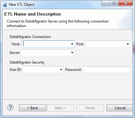
Type, or select from the drop-down list, the DataMigrator host name in the Host field and port in the Port field. Select the Server from the drop-down list. Type the User ID and the Password to access DataMigrator, in the fields provided under DataMigrator Security.
Note: A message window opens when you type or select an invalid credential.
Click Next. The DataMigrator Flows dialog box opens, as shown in the following image.
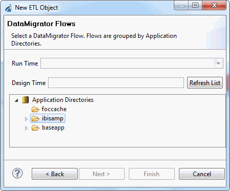
From the Flows list, select the DataMigrator flow that you want to execute from the ETL object. Click Next.
Important: Designer supports ETL objects with names of 45 characters or less in length.
The Properties dialog box opens, as shown in the following image. This dialog box shows the properties of the ETL object you are creating.
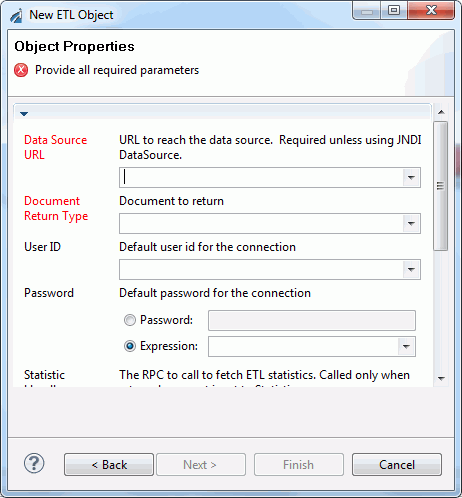
You can change the Document Return Type and Pool Connections properties, if necessary. Click Next.
The ETL Options dialog box opens, as shown in the following image.
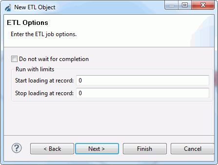
Select Do not wait for completion to start a long-running ETL job asynchronously, in which case the process flow will continue immediately with the next object, or objects, in the flow.
The Run with limits options (Start loading at record and Stop loading at record) allow you to define a range of records for the ETL job. For example, selecting a small set of records might be preferable for testing purposes.
Click Next. The ETL Parameters dialog box opens. Enter parameters for ETL stored procedures and click Next. The ETL Return Codes dialog box opens, as shown in the following image.
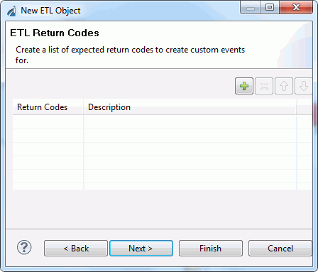
If you want to add a return code to the object, select Click here to Add, under the Return Code column, to activate the field, and enter the return code. Type a description of the return code in the Description column. You can enter several return codes, as needed. Click Finish.
The ETL object appears in the workspace.
Once an ETL object exists, you can configure it to accept dynamic properties. To do this, open the ETL object for editing, and select the Properties tab. Replace one or more of the properties with a special register (SREG), an XPath statement, or any other iWay Functional Language statement. For information on using variables and Xpaths, see Using Variables and XPath.
File Object
The File object allows a process to perform file operations at execution time. The File object icon is shown below.
When you add a File object to a process flow, the New File Object dialog box opens, as shown in the following image.
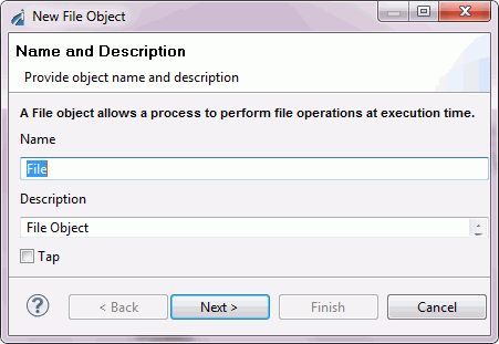
Type a Name to identify the File object and, optionally, type a brief Description.
Click Next. The File Object Type dialog box opens, as shown in the following image.
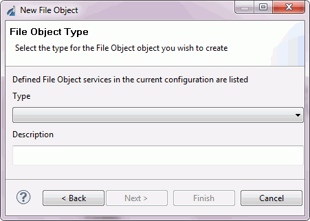
From the Type drop-down list, select the file type. The file types are:
- File Emit Agent. Emits a document to a physical file.
- PF File Ops Agent. Performs operations on the specified file(s) including copy, move, rename, prepend, append, delete, size, and exist.
- PF File Read Agent. Embeds a specified binary, xml, or text file in the input document.
Click Next. The Properties dialog box opens. The properties that appear depend on the File type you selected. The following image is the Properties dialog box for File Read.
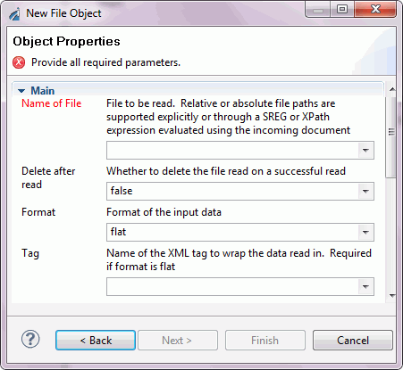
Note: All fields with titles in red are required parameters.
Define the appropriate properties and click Finish. The File object icon appears in the workspace.
FTP Object
The File Transfer Protocol (FTP) object allows the process flow to send or receive data using FTP. The FTP object icon is shown below.
When you add an FTP object to a process flow, the New FTP Object dialog box opens, as shown in the following image.
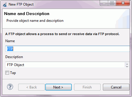
Type a Name to identify the FTP object and, optionally type a brief Description.
Click Next. The FTP Object Type dialog box opens, as shown in the following image.
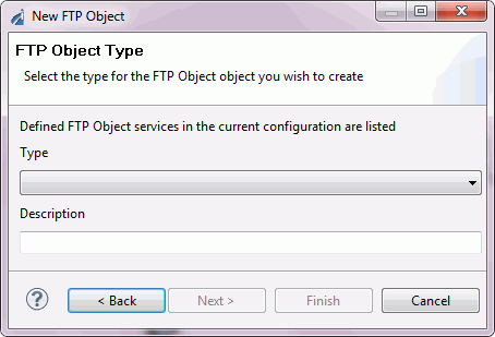
From the Type drop-down list, select the FTP type. The types are:
- FTP Emit agent. Emits via FTP protocol to a given host:port using various common FTP commands.
- PFFTP Ops agent. Performs operations on a specified file(s) including, copy, move, rename, prepend, append, delete, size, and exist.
- PFFTP Read agent. Embeds a specified binary, or text file, in the input document.
Click Next. The Properties dialog box opens. The properties that appear depend on the FTP type you selected. The following image is the Properties dialog box for FTP Reader.
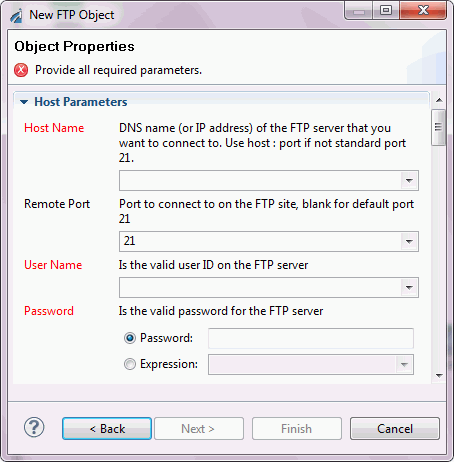
Note: All fields with titles in red are required parameters.
Type or select the property values to define the FTP object. Click Finish when all properties are defined. The FTP object icon appears in the workspace.
HTTP Object
The Hyper Text Transfer Protocol (HTTP) object allows a process flow to send or receive data using HTTP. The HTTP object icon is shown below.
When you add an HTTP object to a process flow, the New HTTP Object dialog box opens, as shown in the following image.
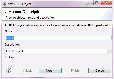
Type a Name to identify the HTTP object and, optionally, type a brief Description.
Click Next. The HTTP Type dialog box opens, as shown in the following image.
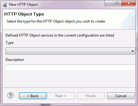
From the Type drop-down list, select the HTTP type. The HTTP types are:
- HTTP Emit Agent. General HTTP Emitter for use with the agent stack.
- HTTP Read Agent. Reads an HTTP source via HTTP GET. Returns result.
Click Next. The Properties dialog box opens. The properties that appear depend on the HTTP type you selected.
The following image is the Properties dialog box for HTTP Read Agent.
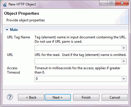
Note: All fields with titles in red are required parameters.
Define the appropriate properties and click Finish. The HTTP object icon appears in the workspace.
Iterator Object
The Iterator object allows you to repeat certain portions of a complete process flow or in specified sections of an input document. The number of times a flow is repeated can be based on either a count, the result of a Boolean expression, or the structure of the document itself.
Important: The iWay Registry contains only those classes that support the iWay Samples. Therefore, when using Iterator objects in a Registry‑based project, you must add the iterator classes to the Registry from the base configuration through the iWay Service Manager Administration Console (select Tools, Archive Manager, Import components from managed server, click Next, and select base). See the iWay Service Manager User’s Guide for details.
The Iterator object icon is shown below.
The Iterator object works in conjunction with the Loop relation, which defines the path of the flow that is to be iterated. The following image is an example of a process flow using an Iterator object.
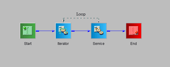
When the iterator completion condition is met, execution of the flow continues with the objects after the loop. Despite the appearance of the diagram in the Designer workspace at completion, the flow ‘jumps’ over the objects inside the loop. Otherwise, the logic inside the loop would be erroneously executed one additional time.
Some guidelines for using Iterator objects in a process flow are:
- The loop must begin with an Iterator object. The flow cannot branch into an iteration loop.
- Iterator loops can be nested. However, loop lines cannot cross.
- Only Execution objects (Service, Iterator, Transform, Process, WebService, SQL, ETL, BI, Email, FTP, File, HTTP, Emitter, Queue) can end a loop.
- Loops cannot be drawn from Control objects (Join, Junction, Decision Switch, Decision Test, Set, Sync, Debug).
When you add an Iterator object to a process flow, the New Iterator Object dialog box opens, as shown in the following image.
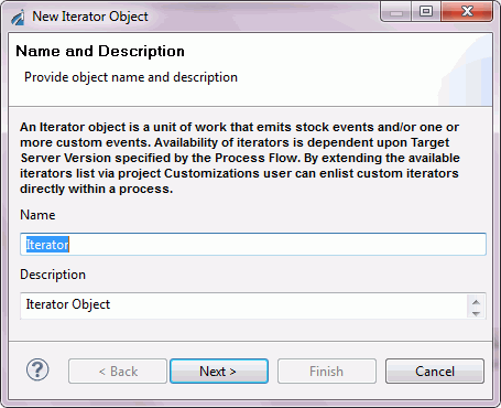
Type a Name to identify the Iterator object and, optionally, type a brief Description.
Once you have named the new Iterator object, click Next. The Iterator Object Type dialog box opens, as shown in the following image.
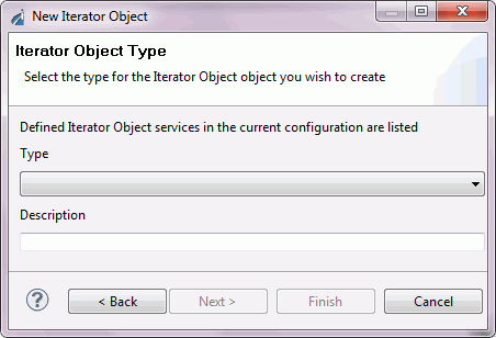
The Iterator objects are instantiated on the iWay Service Manager server as agents. Iterator agents are distinguished from other agents by their name, which contains the string “ITER”. The available Iterator types are:
- Attachment Iterator {com.ibi.agents.XDIterAttachments}. Handles each attachment of the current document iteratively.
- Chunk Iterator {com.ibi.agents.XDIterChunk}. Splits the input document into chunks of equal size.
- Condition Iterator {com.ibi.agents.XDIterCond}. Iterates a loop while (or until) a condition is met.
- Counter Iterator {com.ibi.agents.XDIterCount}. Iterates the loop an exact number of times. Analogous to the programming construct called a "for/next loop."
- FTP Emit Iterator {com.ibi.agents.XDIterFTPEmitStdAgent}. Emits via FTP protocol to a given host:port using various common FTP commands.
- Island Iterator {com.ibi.agents.XDIterIsland}. Iterates the loop for each island within the document, replacing the island with the result of processing the island text. Islands can be used for Document Enrichment. Islands cannot be nested; only the outermost islands will be iterated.
- Iter RVI Relay {com.ibi.agents.XDIterRVIRelay}. Relays messages for external execution.
- Line Iterator {com.ibi.agents.XDIterLine}. Iterates the loop for each line in the input document. Lines are assumed to be separated by standard end-of-line delimiters.
- SQL Batch Insert Iterator {com.ibi.agents.XDIterSQLBatchAdd}. Batch Add Iterator; Reads SQL rows one at a time and inserts results from the flow.
- SQL Select Iterator {com.ibi.agents.XDIterSQLSelect}. SQL Select Iterator; Sends out rows, one at a time, to the flow.
- Sibling Iterator {com.ibi.agents.XDIterSibSplit}. Iterates the loop for each portion of the XML document on a specified XML tag. Ideal for processing repeating segments within the document.
- Test Iterator {com.ibi.agents.XDIterTest}. Iterates the loop while (or until) a specific condition is met. Analogous to the programming construct called a "while loop."
- XML Iterator {com.ibi.agents.XDIterXMLSplit}. Iterates a loop for each portion of an XML document.
Note: See the iWay Service Manager User’s Guide for information on island, sibling, and status, as used in iWay.
Once you have selected an iterator type, click Next.
The Properties dialog box opens. Each iterator type has its own set of parameters, so this dialog box will only list those parameters associated with the selected iterator. The following image shows the Object Properties dialog box for the Counter iterator type.
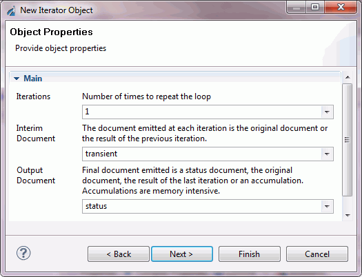
Select or enter the parameters required to configure the Iterator object and click Finish. The Iterator object appears in the workspace.
To view details and examples for iterator object properties, see Iterator Object Properties.
Process Object
The Process object facilitates code reuse and modularity by inserting a published process flow into the current process flow. The affect of using the Process object is much like using a subroutine call in traditional programming languages. The Process object icon is shown below.
When you add a Process object to a process flow, the New Process Object dialog box opens, as shown in the following image.
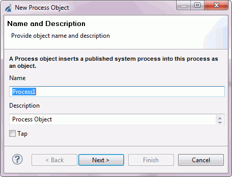
Type a Name to identify the Process object and, optionally, type a brief Description.
Click Next. The Process Object Properties dialog box opens, as shown in the following image.
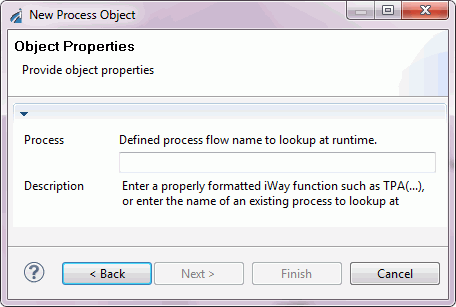
Key in the process flow you want to associate with the Process object and click Finish.
Note: Only previously published process flows are available to the Process object. In the case of a Registry-based project, the process flow must have been published to the Registry. In the case of a server-based project, the process flow must have been published to the system area of the named Server Configuration, for example, base.
The Process object icon appears in the workspace.
Queue Object
The Queue object sends or receives documents using a supported queue type. The Queue object icon is shown below.
When you add a Queue object to a process flow, the New Queue Object dialog box opens, as shown in the following image.
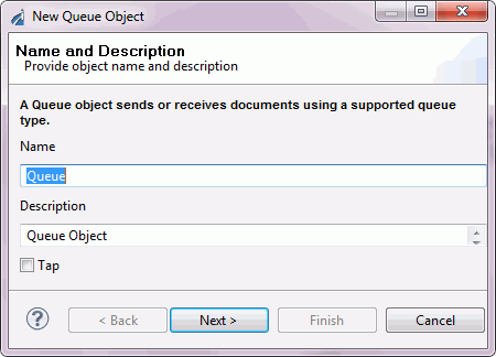
Type a Name to identify the Queue object and, optionally, type a brief Description.
Click Next. The Queue Object Type dialog box opens, as shown in the following image.
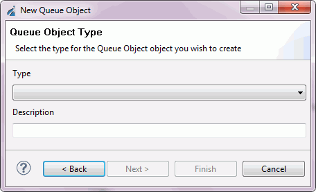
Select the queue type from the Type drop-down list.
The available queue types are:
- Sonic MQ. Emits
a document using Sonic MQ.
The Sub Type selection is Output.
- Oracle AQ. Emits
a document using Oracle Advanced Queuing facility (AQ).
The Sub Type selection is Output.
- JMS Queue. Reads
a file from a Java Message Service queue and returns a result.
The Sub Type selection is #STARTUP_JMS_L.
- Tibco Rendezvous. Emits
a document using Tibco Rendezvous messaging.
The Sub Type selection is Output.
- MQ Series. Reads
a single file from an MQSeries queue.
The Sub Type selection is Output.
Click Next. The Properties dialog box opens. The properties that appear depend on the Queue Type you selected. The following image is the dialog box that appears when you select SonicMQ.
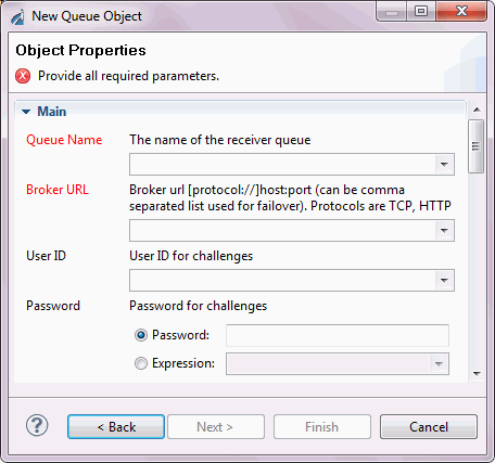
Note: All field titles in red are required parameters.
Define the appropriate properties and click Finish. The Queue object icon appears in the workspace.
ReportCaster Object
The ReportCaster object immediately submits one or more selected schedules to a ReportCaster Distribution server for execution. The ReportCaster object icon is shown below.
When you add a ReportCaster object to the process flow, the New ReportCaster Object dialog box opens, as shown in the following image.
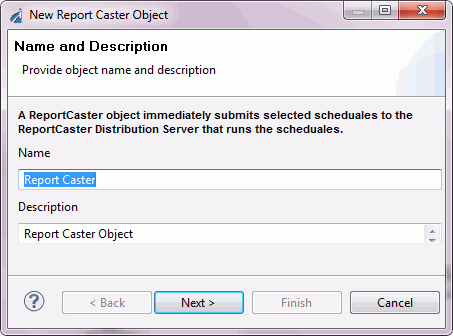
Type a Name to identify the ReportCaster object and, optionally, type a brief Description.
Click Next. The ReportCaster Server Connect dialog box opens, as shown in the following image.
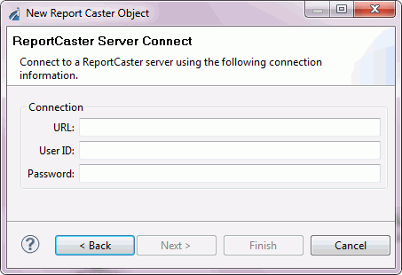
Enter the URL to the ReportCaster server, and the login credentials to access the server.
Click Next. The ReportCaster Schedules dialog box opens displaying the schedules available to you. The following image shows an example of this dialog box.
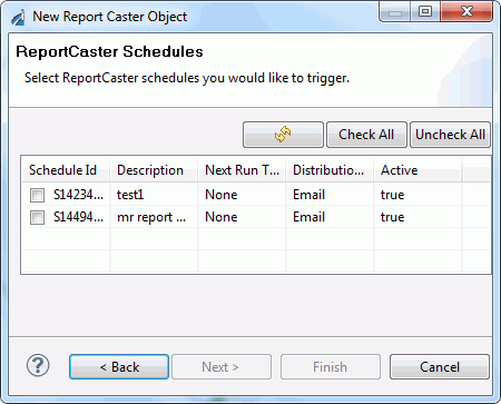
Select the schedule(s) you want to trigger with this ReportCaster object by selecting the corresponding check box in the Schedule Id column.
Click Finish. The ReportCaster object icon appears in the workspace.
Script Object
The Script object allows you to execute java script on a process flow’s object. The Script object icon is shown below.
When you add a Script object to the process flow, the New Script Object dialog box opens, as shown in the following image.
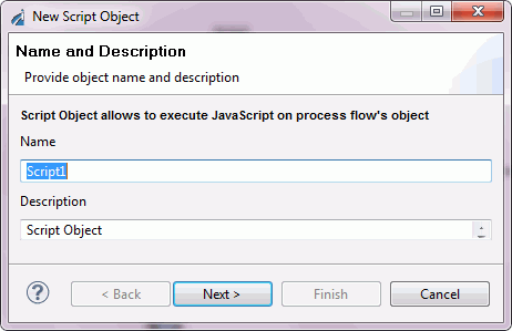
Type a Name to identify the Script object and, optionally, type a brief Description.
Click Next. The Script Object Properties dialog box opens, as shown in the following image.
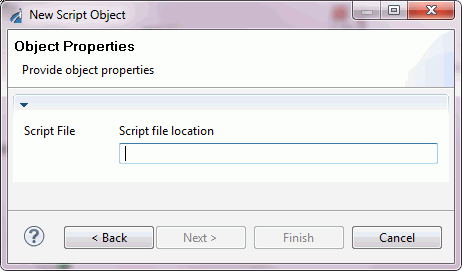
Enter the Script file location and click Next to configure further, or click Finish.
The Pre-Execution dialog box opens. The following image shows an example of this dialog box.
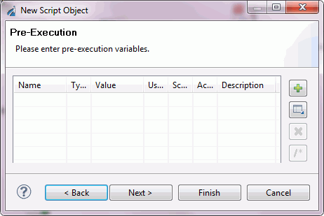
Enter the variables in their respective columns. Click Next to configure further, or click Finish.
The Post-Execution dialog box opens. The following image shows an example of this dialog box.
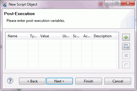
Enter the variables in their respective columns. Click Next to configure further, or click Finish.
The Debug Settings dialog box opens. The following image shows an example of this dialog box.
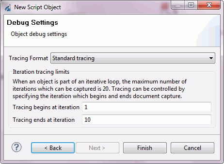
Choose the Tracing Format from the drop-down list. The choices are
- Standard tracing.
- Standard tracing displayed in hex format.
- Just the output document.
- None, under any circumstances.
Select the iterations in which you want the tracing to commence and end.
Click Finish. The Script object icon appears in the workspace.
Service Object
The Service object is a unit of work that emits default events and/or one or more custom events. The available services are based on the server side configuration. By extending the configuration, you can enlist custom services directly within a process flow.
Important: The iWay Registry or configuration contains only those service classes that are defined in that Registry or configuration. If the Registry or configuration requires additional service classes for a particular process flow, you must add them through the iWay Service Manager Administration Console (select Tools, Archive Manager, Import components from managed server, click Next, and select base.) See the iWay Service Manager User’s Guide for details. For example, initially the iWay Registry contains only those service classes associated with the iWay samples. Therefore, you must add any additional classes required when new Service objects are added to projects in the Registry.
The Service object icon is shown below.
When you add a Service object to a process flow, the New Service Object dialog box opens, as shown in the following image.
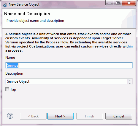
Type a Name to identify the Service object and, optionally, type a brief Description, or accept the default option.
Click Next. The Service Type dialog box opens, as shown in the following image.
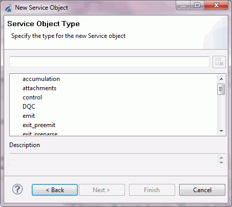
Select a defined service from the list.
Note: If you have selected or defined a Control agent, in order to protect the run-time configuration from tests within Designer, the Control agent will only work correctly after the process flow of which it is a part has been published to a listener. If you choose to Build, Test, and Run the flow before publishing to a listener, the flow will result in an error.
Click Next.
The properties that appear in this dialog box depend on the service you select. The following image shows the Properties dialog box for a control service.
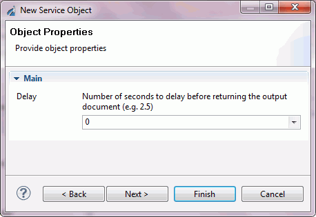
Enter the properties to define the service, and click Finish. The Service object icon appears in the workspace.
SQL Object
An SQL object is used to execute simple SQL requests within a process flow. The request can use XPath values within the document to drive the request. The SQL object icon is shown below.
The SQL object enables the execution of standard SQL statements against a target RDBMS from inside your process flow. Supported commands include Data Manipulation Language (DML), Data Definition Language (DDL), and other miscellaneous commands (GRANT, COMMIT, and so on) against the database. Care should be taken when designing process flows that perform potentially destructive operations on the database (DELETE, DROP TABLE, and so on) to prevent unintended data loss. Typical applications include use of the SELECT, INSERT, UPDATE, and DELETE commands.
To invoke stored procedures, the CALL statement is provided and can include properties that are defined for input or input and output use. CALL statement "output-only" parameters are currently not supported, due to limitations in binding iWay registers to SQL statements.
When you add an SQL object to a flow, the New SQL Object dialog box opens, as shown in the following image.
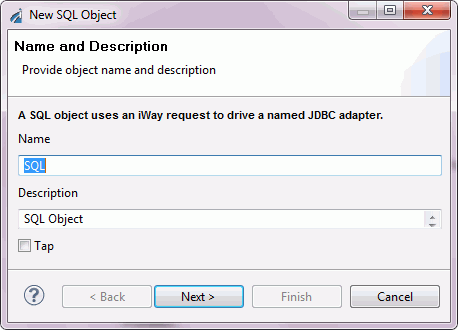
Type a Name to identify the SQL object and, optionally, type a brief Description.
Click Next. The Data Source URL dialog box opens, as shown in the following image.
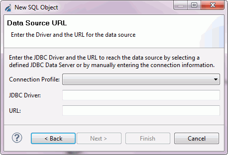
Specify a Java Database Connectivity (JDBC) driver and URL to access the data source, by either selecting a defined JDBC server from the Connection Profile drop-down list, or entering the connection information in the JDBC Driver and URL fields.
Click Next. The SQL Statement dialog box opens, as shown in the following image.
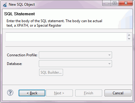
Type the SQL statement and click Next.
The Properties dialog box opens. An example of this window is shown in the following image.
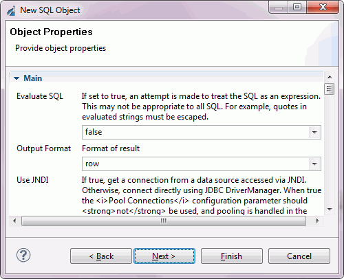
Enter the required properties for the SQL object and click Next. For information on the SQL object properties, see SQL Object Properties.
Another Properties dialog box opens, in which you can define your own properties for the SQL object. An example of this dialog box is shown in the following image.
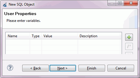
When you have completed defining the properties, click Finish. The SQL object icon appears in the workspace.
Data Integration Object
The Data Integration object iterates over an SQL result set and batch inserts.
The Data Integration object icon is shown below.
When you add a Data Integration object to a process flow, the New Data Integration Object dialog box opens, as shown in the following image.
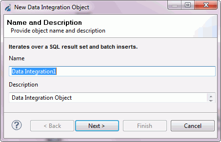
Type a Name to identify the Data Integration object and, optionally, type a brief Description.
Once you have named the new Data Integration object, click Next. The Select Statement dialog box opens, as shown in the following image.
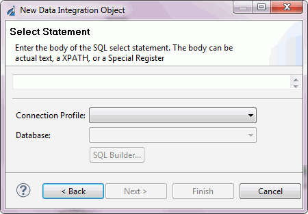
Enter the body of the SQL statement. The body can be actual text, an XPATH, or a Special Register. If required, select the Connection Profile and the Database.
Click Next. The Insert Statement Parameters dialog box opens, as shown in the image below.
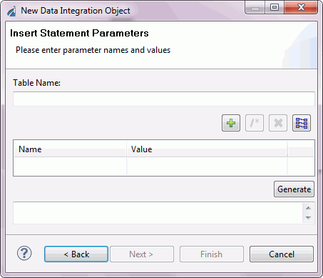
Enter the Table Name, parameter name, and parameter values. Click the Generate button. The input statement, with the specified parameters, is displayed in the box below.
Click Next. The Properties dialog box opens, as shown in the following image.
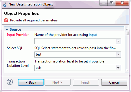
Note: All properties with titles in red are required parameters.
When you are finished selecting all of the properties, click Next. The Debug Settings dialog box opens, as shown in the following image.
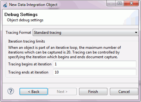
Choose the Tracing Format from the drop-down list. The choices are:
- Standard tracing.
- Standard tracing displayed in hex format.
- Just the output document.
- None, under any circumstances.
Select the iterations in which you want the tracing to commence and end.
Click Finish. The Data Integration object icon appears in the workspace.
Transform Object
The Transform object applies a selected transform to the document it receives within the process flow. It also allows you to launch iWay Transformer to create a new transform for this object.
The Transform object icon is shown below.
When you add a Transform object to a process flow, the New Transform Object dialog box opens, as shown in the following image.
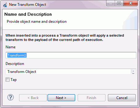
Type a Name to identify the Transform object and, optionally, type a brief Description.
Once you have named the new Transform object, click Next. The Object Properties dialog box opens, as shown in the following image.
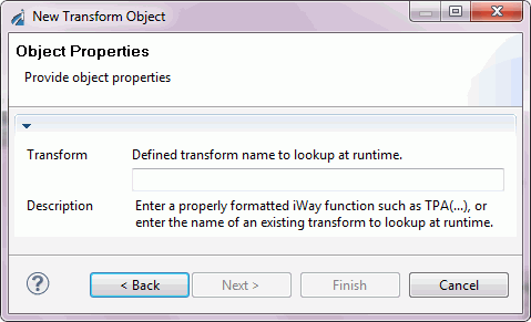
The Pre-Execution dialog box opens, allowing you to enter the pre-execution properties for the transform type you selected. An example of this dialog box is shown in the following image.
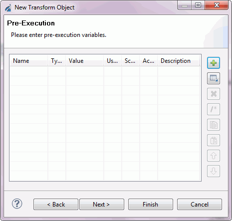
When you are finished entering the transform properties, click Next.
The Post-Execution dialog box opens, allowing you to enter the post-execution properties for the transform type you selected.
Click Finish. The Transform object icon appears in the workspace.
Web Service Object
The Web Service object allows the execution of a web service from within a process flow. The web service can be an external service, such as a third party web service, or a web service hosted by iBSP.
The Web Service icon is shown below.
When you add a Web Service object to a flow, the New Web Service Object dialog box opens, as shown in the following image.
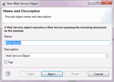
Type a Name to identify the Web Service object and, optionally, type a brief Description.
Click Next. The WSDL Location dialog box opens, as shown in the following image.
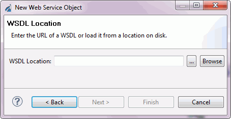
In the WSDL location field, provide the location of the Web Service Descriptive Language (WSDL) file that describes the web service you are adding to the process flow, in one of the following ways:
- Type a URL.
- Browse to a WSDL.
- Point to an iBSP repository.
As an option, you can provide the location to a Web Service Descriptive Language (WSDL) file that describes the web service you are adding to the process flow. You can either manually enter the location, click the ellipses (...) to load the Local WSDL File, or click Browse to browse to a WSDL file.
If you select the ellipses (...), a local directory of your project opens in which you can locate the WSDL file.
If you select Browse, the Windows box of all directories of your computer opens. This dialog box allows you to select a WSDL from an instance of iWay Business Service Provider.
Click Next.
The WSDL Services dialog box opens, as shown in the following image.
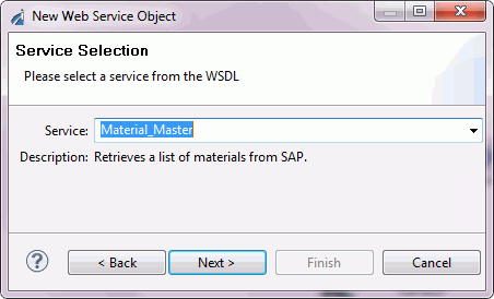
Select a service from the Service drop-down list and click Next.
The Web Service End Point dialog box opens, as shown in the following image.
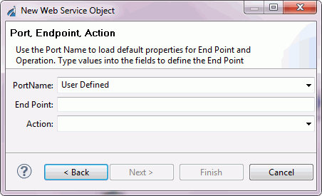
The PortName, End Point, and Action fields are automatically populated with the related values when you select the Port Name. You can also manually define all fields when you select User Defined. Click Next.
The Web Service Header dialog box opens, as shown in the following image.
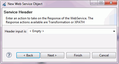
Select or type the header information in the Header Input is field and click Next.
The Web Service Body dialog box opens, as shown in the following image.
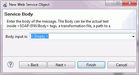
From the Body Input is drop-down list, select the body of the web service.
Note: The body can be the actual text inside the <SOAP-Env:Body> tags, a transformation, a path to a file containing the body, an XPath, or an SREG.
Click Next. The Web Service Response dialog box opens, as shown in the following image.
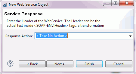
From the Response Action drop-down list, select an action to take on the response of the web service. Click Next. The Web Service Fault dialog box opens, as shown in the following image.
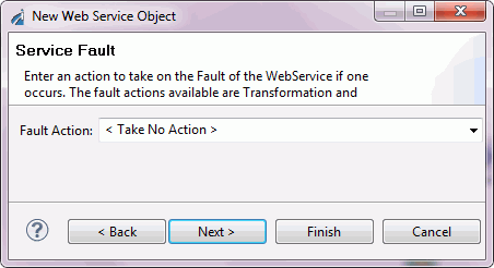
From the Fault Action drop-down list, select an action to take if there is a fault with the web service. Click Next.
The Proxy Configuration dialog box opens.
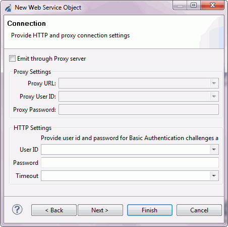
If you are using a proxy server for the web service, select Emit through Proxy server, and enter the Proxy URL and the ID and password for accessing the proxy server. Click Next.
The Strip SOAP Envelope dialog box opens, as shown in the following image.
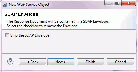
Check Strip the SOAP Envelope if you want to have the response document removed from the SOAP envelope. Click Finish.
The Web Service object appears in the workspace.
Note: For Web Service objects, Designer will use all faults defined in the WSDL as custom events. Edges that refer to specific faults can be constructed by selecting from the OnCustom list of cases. For more information, see Building Relationships Between Objects.