Configuring and Deploying the iWay Application System Adapter for J.D. Edwards EnterpriseOne
|
How to: |
This section describes how to configure and deploy the iWay Application System Adapter for J.D. Edwards EnterpriseOne through the iWay Service Manager (iSM) Administration Console.
Procedure: How to Add the J.D. Edwards EnterpriseOne Adapter
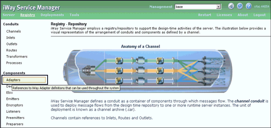
- Under the Components section on the
left pane, click Adapters, as shown in the
following image.
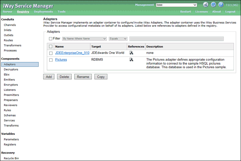
The Adapters pane opens and shows the adapter object, as shown in the following image.
- Select the configured J.D. Edwards EnterpriseOne adapter
target that is available (for example, JDEEnterpriseOne_910)
and click OK.
The following pane opens, which provides a summary of the configured connection parameters for the selected J.D. Edwards EnterpriseOne adapter target.
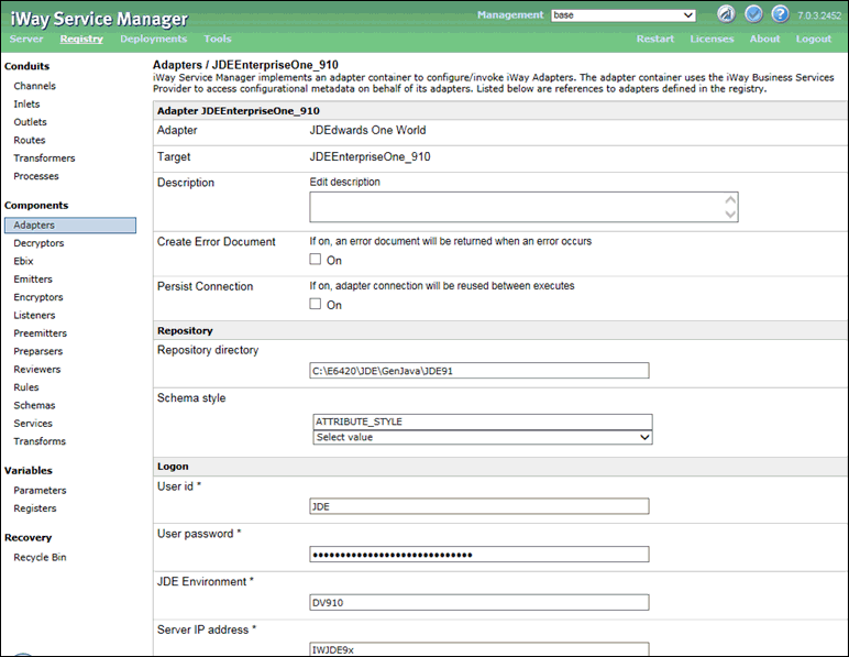
- Verify the configured connection parameters.
Procedure: How to Configure the Listener
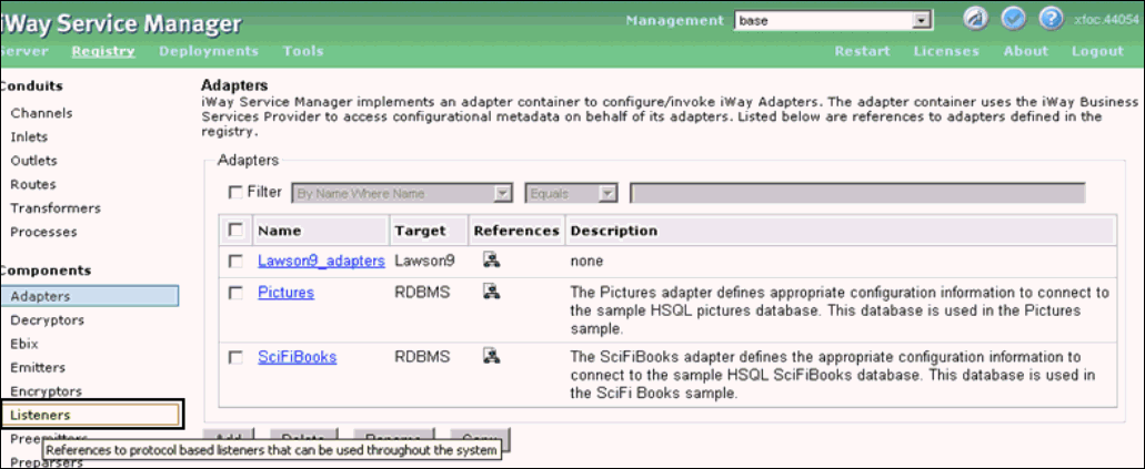
- Under the Components section on the
left pane, click Listeners, as shown in the
following image.
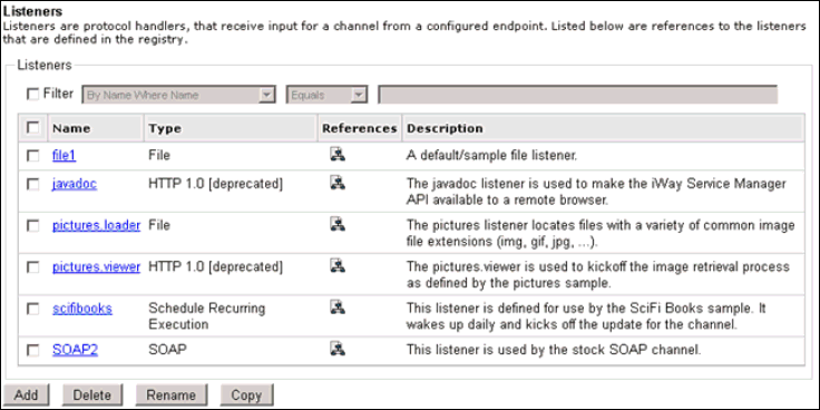
The Listeners pane opens, as shown in the following image.
- Click Add.
The Select listener type pane opens, as shown in the following image.
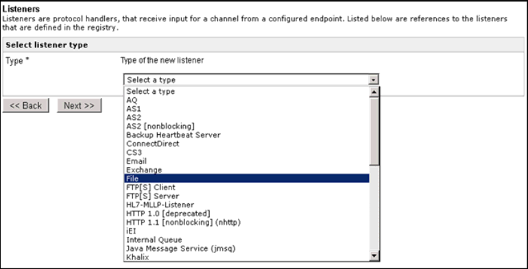
- Select File from the Type drop-down
list and click Next.
The Configuration parameters pane for the File listener opens, as shown in the following image.
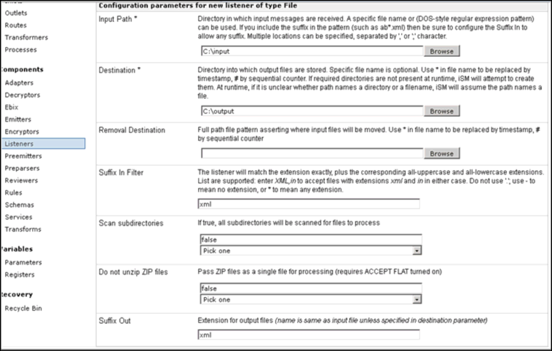
- In the Input Path field, specify the directory where
the input messages are received. For example:
C:/input
- In the Destination field, specify the directory where
output files are stored. For example:
C:/output
- In the Suffix Out field, specify the extension for output
files. For example:
xml
- Click Next.
The following pane opens, which allows you to specify a name for the new listener.
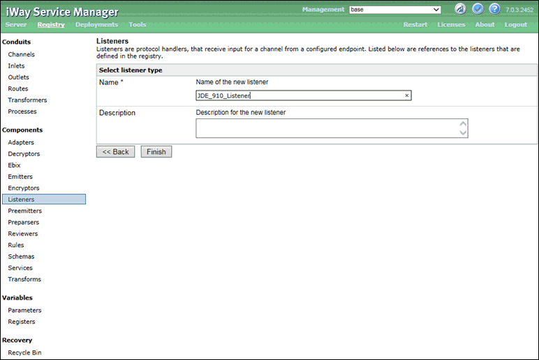
Specify a listener name (for example, JDE_910_Listener) and click Finish.
Procedure: How to Configure a Process and Define a Route
- Under the Conduits section on the left
pane, click Processes, as shown in the following
image.
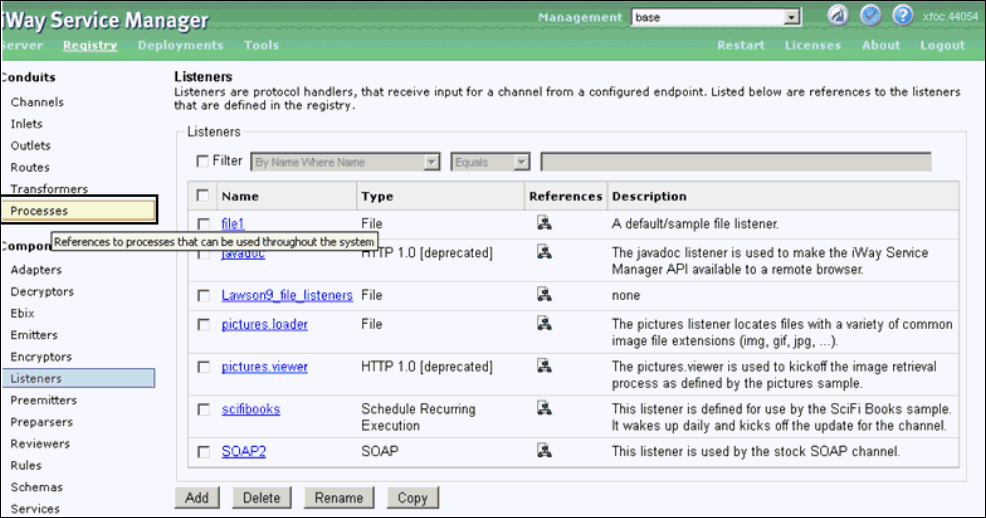
The Processes pane opens, as shown in the following image.
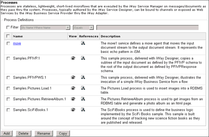
- Click Add.
The New Process Definition pane opens, which allows you to specify a name for the new process definition, as shown in the following image.
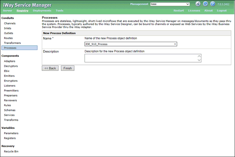
- Specify a process name (for example, JDE_910_process) and click Finish.
- The Construct Process pane opens, which allows you to
construct the new process (JDE_910_process) by adding supported
components, as shown in the following image.

- Click Add.
The Assign service object reference pane opens, as shown in the following image.
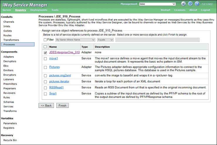
- Select JDEEnterpriseOne_910 and click Finish.
- Under the Conduits section on the left pane, click Routes,
as shown in the following image.
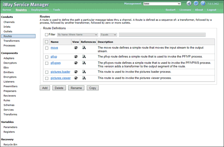
- Click Add.
The New Route Definition pane opens, as shown in the following image.
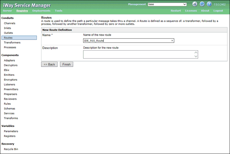
- Specify a route name (for example, JDE_910_Route) and
click Finish.
The Construct Route pane opens, which allows you to construct the new route (JDE_910_Route) by associating a configured process, as shown in the following image.
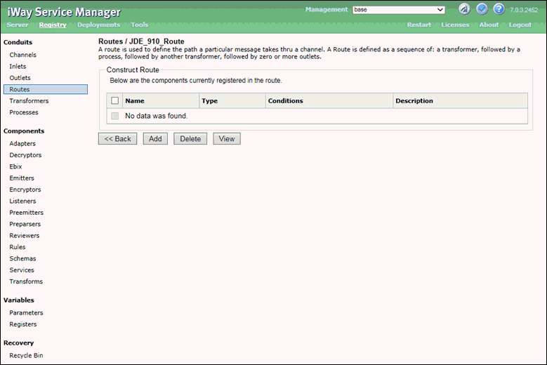
- Click Add.
The Select component type pane opens, as shown in the following image.
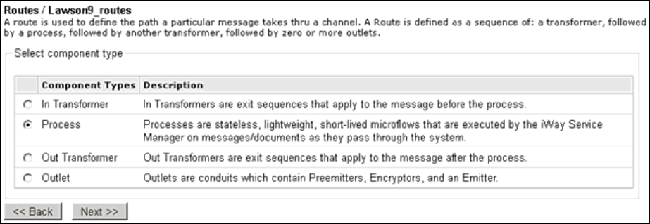
- Select Process and then click Next.
The Select a process definition pane opens, as shown in the following image.
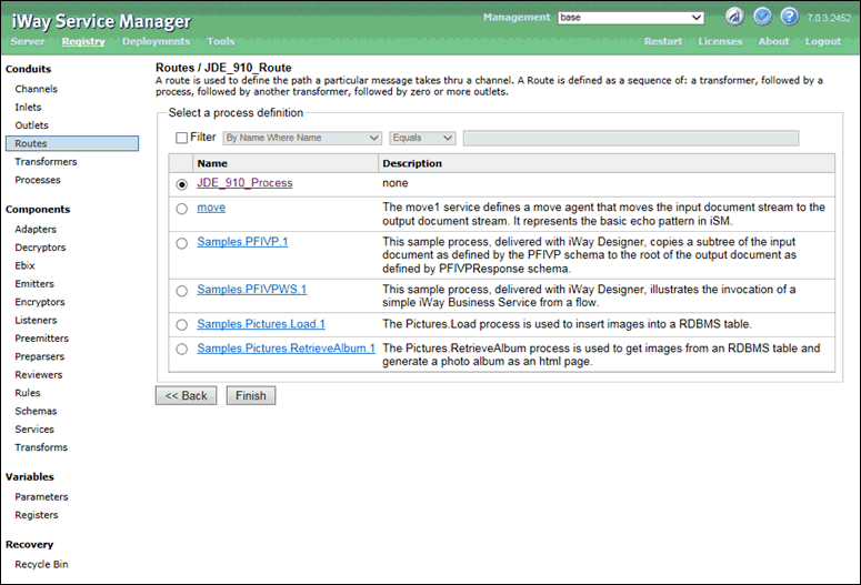
- Select the configured process (JDE_910_Process) and click Finish.
Procedure: How to Define an Inlet
- In the
Conduits section of the left pane, click Inlets.
The Inlets pane opens, as shown in the following image.
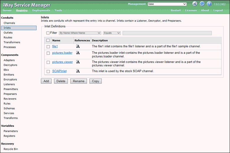
- Click Add.
The New Inlet Definition pane opens, as shown in the following image.
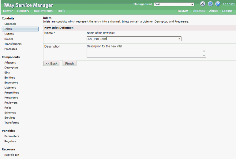
- Specify
an inlet name (for example, JDE_910_inlet) and click Finish.
The Construct Inlet pane opens, which allows you to construct the new inlet (JDE_910_Inlet) by associating supported inlet components, as shown in the following image.

- Click Add.
The Select component type pane opens, as shown in the following image.
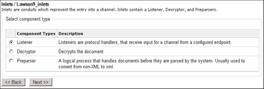
- Select Listeners and
then click Next.
The Select a listener definition pane opens, as shown in the following image.
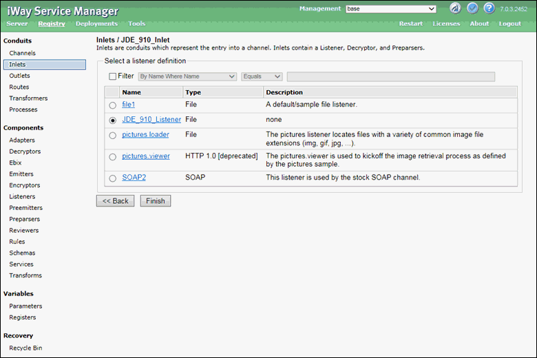
- Select the configured listener (for example, JDE_910_Listener) and click Finish.
Procedure: How to Construct a Channel
- Under the Conduits section in the left
pane, click Channels.
The Channels pane opens, as shown in the following image.
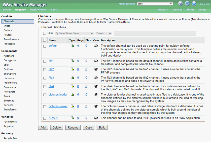
- Click Add.
- Specify a channel name (for example, JDE_910_Channel)
and click Finish, as shown in the following
image.
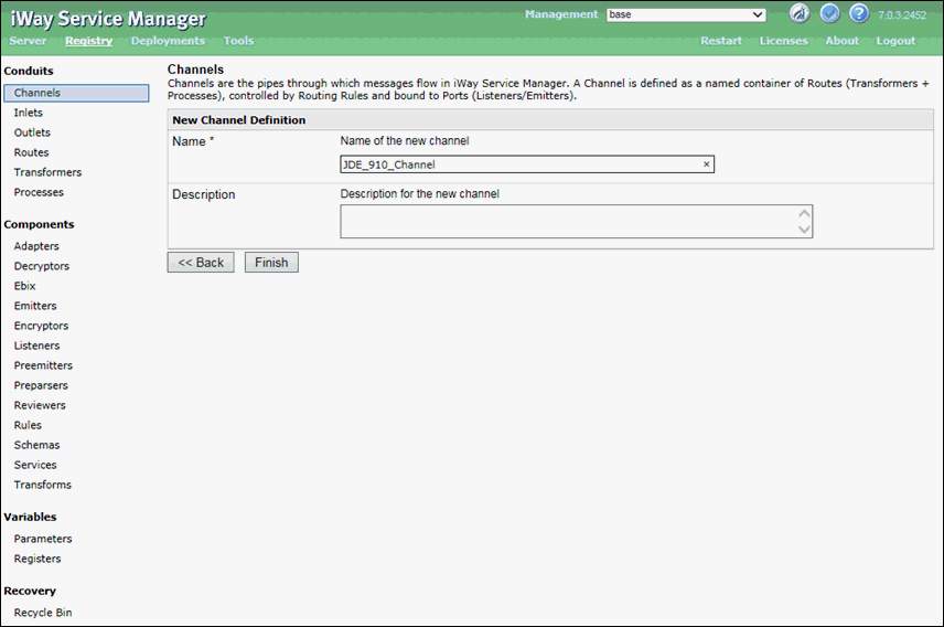
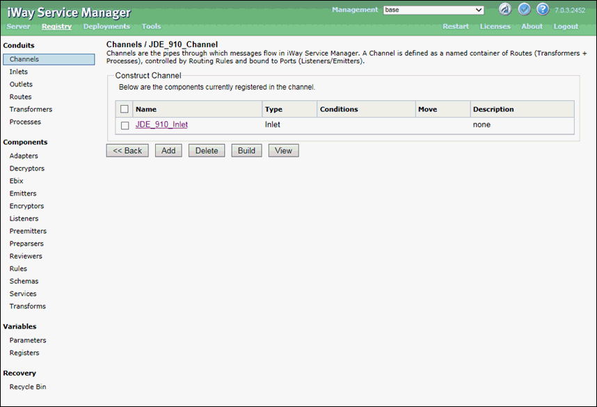
The Construct Channel pane opens, which allows you to construct the new channel (JDE_910_Channel) by associating supported channel components.

- Click Add.
The Select component type pane opens, as shown in the following image.
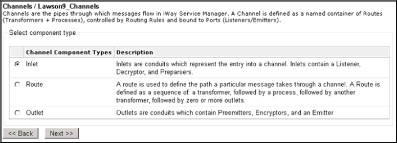
- Select Inlet and then click Next.
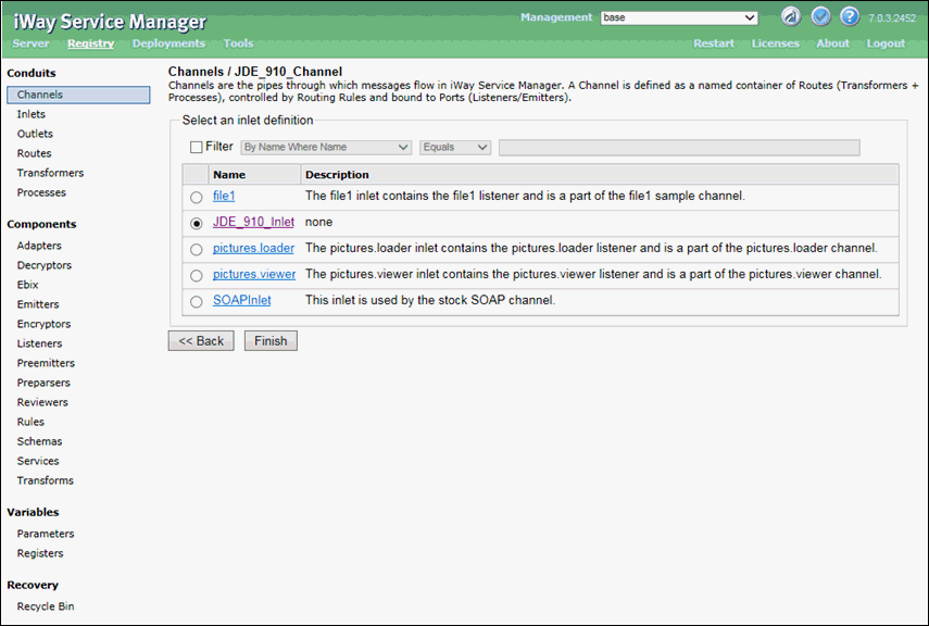
- Select the defined inlet (for example, JDE_910_Inlet)
and click Finish, as shown in the following
image.
You are returned to the Construct Channel pane, as shown in the following image.
- Click Add.
The Select component type pane opens, as shown in the following image.

- Select Route and then click Next.
The select one or more route definitions pane opens, as shown in the following image.
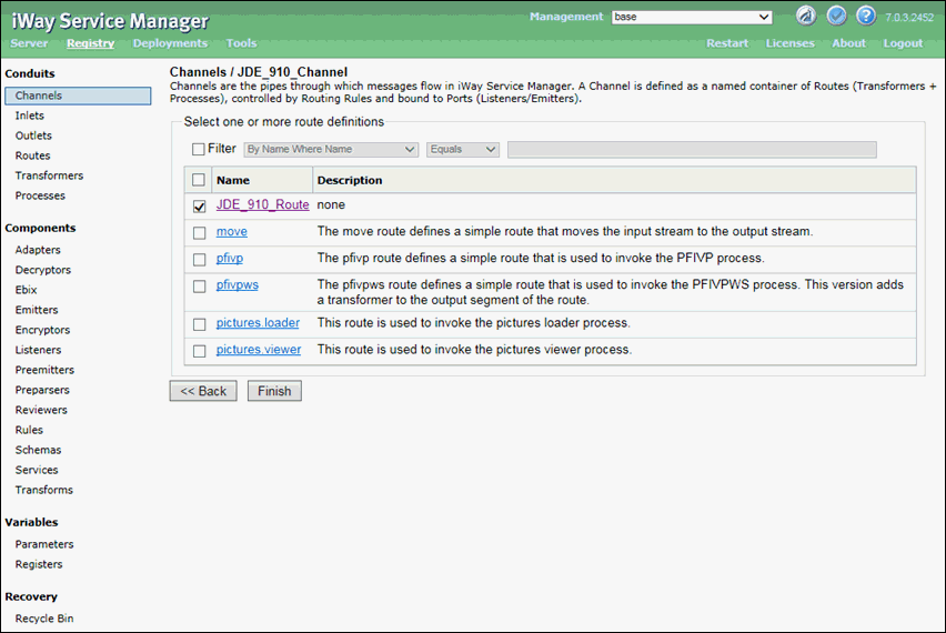
- Select the defined route (for example, JDE_910_Route)
and click Finish.
You are returned to the Construct Channel pane, as shown in the following image.
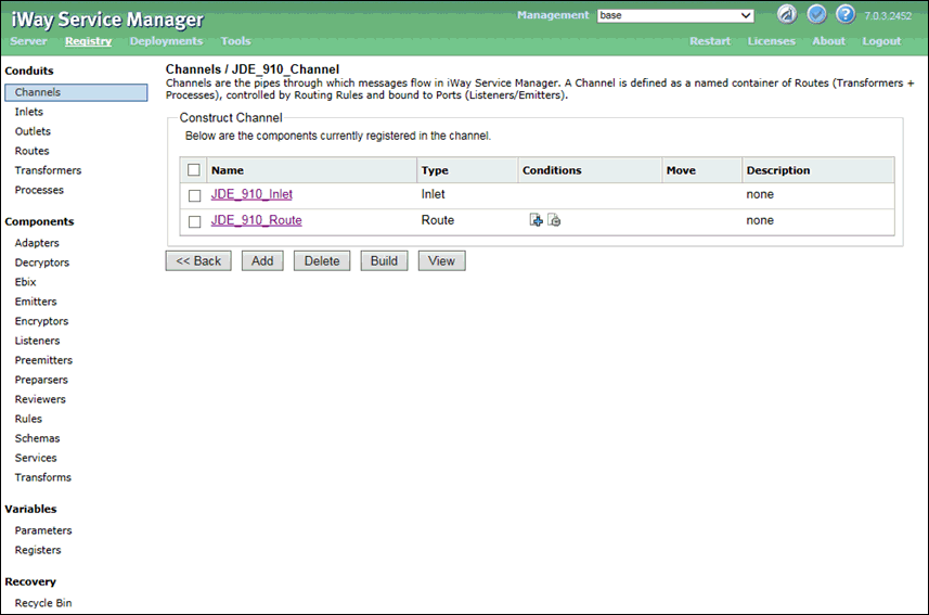
- In the Conditions column, click the minus sign icon for
the route (set as default) and then click Add.
The Select component type pane opens, as shown in the following image.

- Select Outlet and then click Next.
The Select one or more outlet definitions pane opens, as shown in the following image.

- Select default.outlet and then
click Finish.
You are returned to the Construct Channel pane, as shown in the following image.
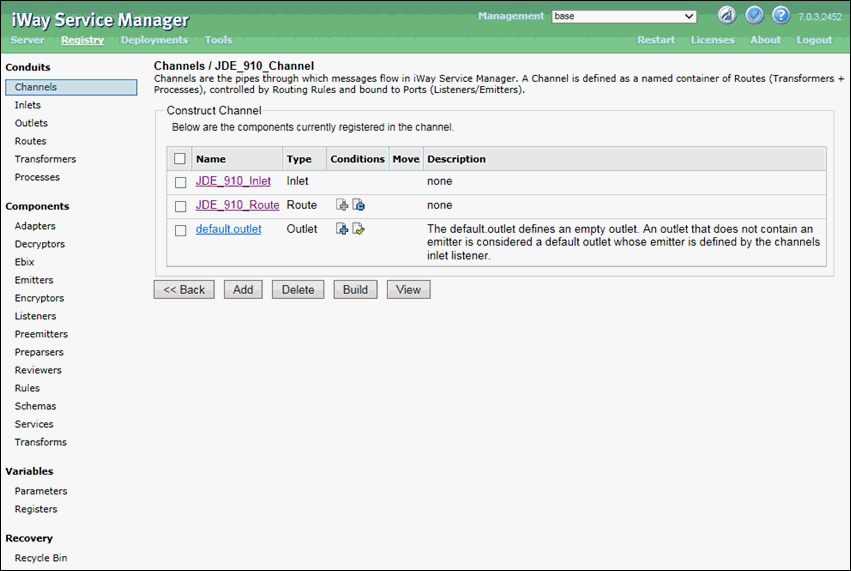
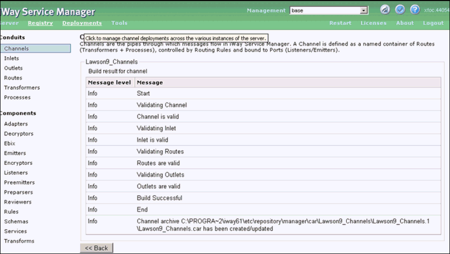
- Select all three channel components and then click Build.
The build results for the channel are displayed, as shown in the following image.
Procedure: How to Deploy and Start a Channel
- Click Deployments in
the top pane, as shown in the following image.

The Channels pane is displayed by default, as shown in the following image.

- Click Deploy.
The Available Channels pane is displayed, as shown in the following image.

- Select JDE_910_Channel and click Deploy.
The Channel Management pane is displayed, as shown in the following image.

- Select JDE_910_Channel and click Start.
The JDE_910_Channel is started successfully, as shown in the following image.

Procedure: How to Test and Validate the Channel
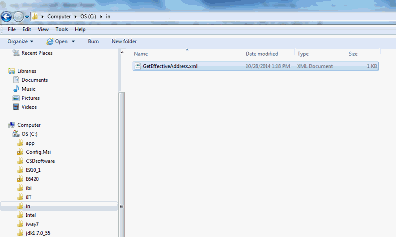
- Copy the input payload for the GetEffectiveAddress.xml
file in the following configured input location:
C:/input
- Check for a response document from the GetEffectiveAddress.xml file
in the following configured destination location:
C:/output
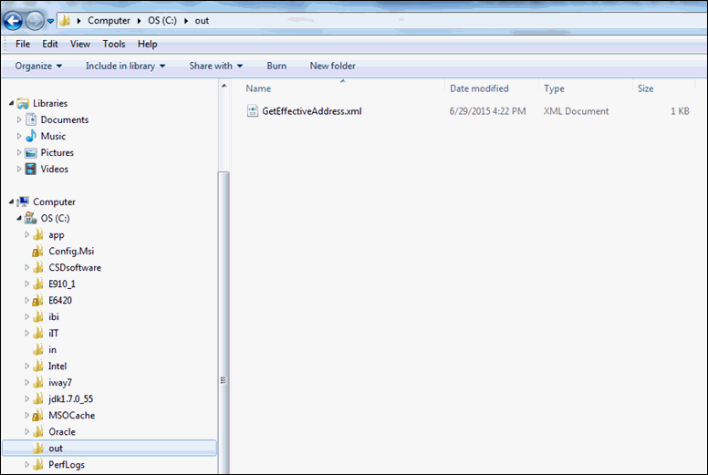
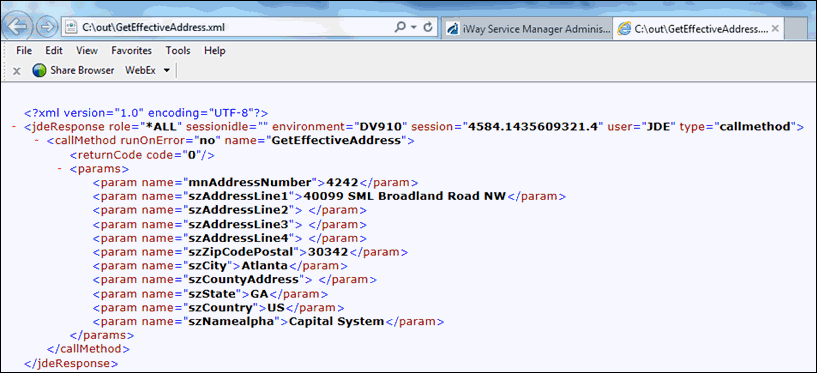
- Open and view the successful response document from the GetEffectiveAddress.xml
file, as shown in the following image.
